Implementing HIL Testing for Power Electronics with CompactRIO
Published by: Sohoprolab Editorial Team | Date: July 8, 2025
Introduction
Power electronics such as inverters, DC/DC converters, and motor drives play a critical role in EVs, renewable energy systems, and industrial automation. Testing these devices under realistic, dynamic conditions requires more than benchtop equipment — it demands a real-time Hardware-in-the-Loop (HIL) simulation environment. CompactRIO (cRIO), with its reconfigurable I/O and embedded real-time control, is uniquely suited for building flexible, deterministic HIL systems for power electronics R&D and validation.
Why Use HIL for Power Electronics?
HIL testing replaces physical subsystems with real-time models, enabling rapid, safe, and repeatable test of embedded control systems. For power converters, HIL helps verify:
- Response to switching and modulation signals
- Fault handling (shorts, overvoltage, open-phase)
- Stability under load and transient conditions
- Compliance with control firmware specifications
This approach reduces risk of damaging expensive power stages during early firmware development and accelerates validation cycles.
CompactRIO Architecture for HIL
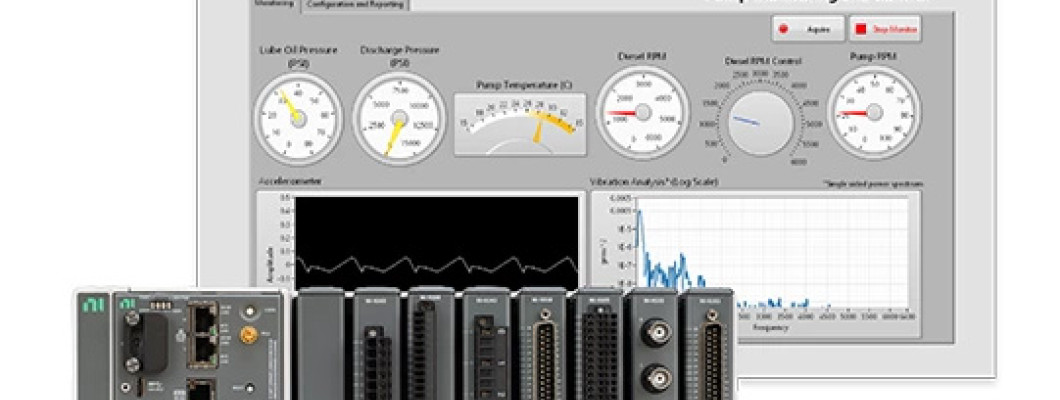
CompactRIO combines an RT controller, Xilinx FPGA, and I/O modules in a rugged chassis. Typical HIL setups use:
- NI 9263, NI 9269: Analog outputs for simulating voltage/current waveforms
- NI 9220, NI 9239: High-speed analog inputs for sensing control outputs
- NI 9401, NI 9472: Digital I/O for PWM, fault injection, and handshake logic
- FPGA: Executes real-time models of inductive loads, power switches, and control loops
Simulation models can be created in LabVIEW FPGA, VeriStand, or imported from Simulink with HDL Coder.
Learn more about compatible modules in our CompactRIO section.
Modeling Power Electronics in Real Time
Accurate real-time models are essential for meaningful HIL. Models often include:
- Switching devices: IGBT/MOSFET states, dead-time, switching losses
- Filters: LC, RLC components with nonlinearities
- Control targets: PID, field-oriented control (FOC), MPPT
- Fault mechanisms: Short circuit, overvoltage, thermal shutdown
LabVIEW FPGA supports fixed-point arithmetic, fast control loops (µs range), and cycle-accurate PWM capture — making it suitable for emulating real-world system dynamics.
Advantages of cRIO for Power HIL
- Embedded determinism: FPGA logic ensures sub-microsecond timing
- Rugged I/O: 24V, industrial-level voltage/current range modules
- Fault simulation: Inject failures without hardware risk
- Scalability: From 1-phase to 3-phase HIL or multi-channel systems
- LabVIEW integration: Easy UI, logging, and model deployment
Use cases range from inverter gate driver testing to grid-tied converter simulation in clean rooms or EMC labs.
FAQs: HIL Testing with CompactRIO
- Can I use cRIO to test high-voltage inverters?
- Yes, but the cRIO simulates signals — not the power stage itself. Use isolation and interface circuits where needed.
- What timing resolution is possible?
- FPGA clock rates up to 40 MHz support PWM and high-speed transient simulation at sub-µs resolution.
- Is software-in-the-loop (SIL) also supported?
- Yes. You can test control algorithms in a simulated environment before deploying to the real-time controller.
Conclusion
CompactRIO enables safe, flexible, and high-fidelity HIL testing for power electronics, from early firmware development to production verification. Whether validating motor drives, DC/DC converters, or power inverters, cRIO systems provide the real-time processing and rugged I/O needed for modern electrical validation labs. Explore our CompactRIO and Electronic Test & Instrumentation sections to build your ideal HIL setup.
