Automated PCB Test on PXI: Rack Design Step by Step
Published by: Sohoprolab Editorial Team | Date: July 8, 2025
Introduction
Building a high-performance, scalable automated test rack for printed circuit boards (PCBs) requires careful planning, especially when using the PXI (PCI eXtensions for Instrumentation) platform. PXI allows tight synchronization, modularity, and rapid integration with existing test software. This guide walks through every stage of designing a PXI-based automated PCB test rack, including hardware selection, fixture setup, switching matrix integration, and software control.
Step 1: Define Test Requirements
Begin by outlining the test objectives — are you performing in-circuit tests (ICT), functional tests (FCT), or boundary scan? Define voltage/current ranges, digital pin count, RF/mixed-signal needs, and expected throughput. This dictates the module count, switching configuration, and fixture complexity.
- Typical I/O Requirements: 32–256 digital, 8–24 analog channels
- Test Types: Continuity, power-up verification, signal integrity, RF performance
- Automation Goal: Cycle time, test coverage, data logging
Step 2: Select the PXI or PXIe Chassis
Choose a chassis with enough slots and bandwidth. For high-speed or RF tests, PXIe is preferred due to Gen 3 PCIe backplane support. Typical chassis used in production include:
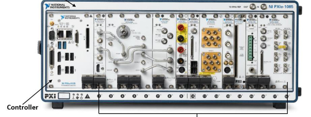
- NI PXIe-1085: 18-slot chassis, Gen 3 ×8 lanes
- Marvin Test GX7005: 14-slot, hybrid-compatible
- Pick power supply redundancy if system runs 24/7
Ensure the chassis has adequate cooling for both modular instruments and the embedded controller.
See our PXI Chassis section for compatible options.
Step 3: Choose PXI Modules for Your Test Needs
PXI modules form the core of your test capabilities. Based on your UUT (unit under test), choose a combination of the following:
- Multimeters: NI PXI-4071, PXIe-4081 for 6.5–7.5 digit resolution
- Switching: PXI matrix or multiplexer cards from Pickering or NI
- Source Measure Units (SMUs): PXIe-4143 for precision sourcing
- Function Generators: PXIe-5433 or equivalent
- RF Analysis: PXIe-5668R or Keysight M9391A for mixed-signal/RF boards
Visit our PXI Modules page to explore available instruments.
Step 4: Design the Fixture Interface
The test fixture acts as the mechanical and electrical interface to the PCB. Consider:
- Bed-of-nails or custom clamshell fixtures
- Connectorization: Mass interconnects via Virginia Panel or MacPanel
- Signal conditioning boards for protection and impedance matching
- ESD & surge protection for delicate analog inputs
Fixtures should allow fast load/unload cycles and accommodate different PCB revisions with minimal effort.
Step 5: Integrate Switching and Signal Routing
For multiplexed tests, integrate switching matrices to route multiple test points to limited measurement channels. PXI switch modules can be configured as:
- 2-wire/4-wire multiplexer
- Matrix switch (e.g., 8×16 or 4×64)
- SPDT or SP4T RF switch banks
Ensure relay timing and isolation meet your UUT signal requirements. High-frequency signals need coaxial or RF-rated switching paths.
Step 6: Embedded Controller & Software Setup
Use an embedded PXI controller (e.g., NI PXIe-8840) or external PC with PXI remote control. Install the following software stack:
- NI TestStand: Test sequence automation
- LabVIEW or Python: Instrument drivers and UI
- Switch Executive: Central switch configuration
- Database logging: PostgreSQL, MySQL, or file-based
Optimize boot time and instrument warm-up routines for minimal cycle delays.
Step 7: Final Rack Integration & Safety
Integrate all components into a 19" rack with proper airflow, EMI shielding, and cable management. Don't forget:
- Label all connectors and test points
- Use interlock and emergency-stop systems
- Grounding paths for test fixture and instrumentation
- Document the wiring and fixture configuration for support
FAQ: PXI-Based PCB Testing
- Can PXI test both analog and digital PCBs?
- Yes. PXI supports a wide range of modules for digital I/O, analog measurements, RF, and mixed-signal testing.
- Is PXI suitable for high-volume production?
- Absolutely. PXI is widely used in automated test equipment (ATE) on SMT and final assembly lines.
- How scalable is a PXI rack?
- You can scale from a 4-slot bench tester to 18-slot full racks with multiple synchronized modules.
Conclusion
Designing a reliable and flexible PXI-based test rack for automated PCB verification is both an engineering and integration challenge. From chassis selection to fixture interfacing and software automation, each step contributes to overall test throughput and maintainability. To browse modular instruments and signal routing options, visit our PXI Platform or explore application-specific tools in the Electronic Test & Instrumentation section.
